Madison, WI 53705, U.S.A.
Phone: (608) 238-2171, Fax: (608) 238-9241
Email: info@powline.com
| Home | Search | News | Products |
|
|
610 N. Whitney Way, Suite 160
Madison, WI 53705, U.S.A. Phone: (608) 238-2171, Fax: (608) 238-9241 Email: info@powline.com |
|||
|
Network Mapping has found that following our adoption of the Power Line Systems suite of programs, our product range and the diversity of engineering studies and commitments that can be produced has surpassed our most fevered expectations.
We used to consider that PLS products were a car, whereas previous software suppliers were a cart. I now know that this car does 3000 miles per gallon and 10,000 miles per hour. Our old horse and cart meanwhile has been found to be blind and lame with only one good wheel.
I have been pleasantly surprised by the capability of PLS-CADD in the transmission design arena. I was particularly impressed with PLS-CADD's structural capability and it's dynamic correlation with all aspects of the line design process. It has given us the ability to be much more productive and efficient, a welcome addition. My only regret is that we hadn't switched to PLS-CADD five years ago.
PLS-CADD, PLS-POLE & TOWER are very powerful stand-alone tools, but when they are combined, they give the engineer total freedom to perform detailed line design quickly and efficiently. The flexibility they provide is only limited to the engineer’s creativity and ingenuity.
The PLS staff is very helpful and prompt in answering any questions and concerns. Their continuing enhancements to the programs show their commitment to the user and to the design field.
I appreciate that Power Line Systems not only seeks to be on the cutting edge of transmission line design, but also take their clients there as well. Their website has so much useful information I am left with bittersweet feelings. I'm excited to learn from and use these resources, but upset that everyone else has access to it. This is only a testament to PLS's desire for their clients to get the most out of their products.
In particular, the information on preliminary model design using USGS information has been most helpful. The online libraries also provide a great starting point for line design. I've learned a few things about setting up criteria files by simply studying the examples on line.
PLS staff is very helpful. Whenever I have a question, my e-mails or calls are always responded to promptly. To sum it up, if you haven't explored the other resources available through PLS, you've merely scratched the surface of your capabilities.
The seamless integration with the line model to get the loads on a tower is invaluable when trying to determine if a particular tower is structurally adequate to support more or larger conductors. We are always trying to get the most capacity out of our lattice towers that were designed back in the days of the slide rule and a "graphical method of joints" with many simplifying assumptions so we could do a two dimensional truss analysis. PLS-CADD and TOWER allow us to quickly determine if a tower will be adequate using a three dimensional finite element analysis. If some members fail, we can use TOWER to determine suitable replacement member sizes.
Before we started using TOWER, PLS-POLE, and PLS-CADD we had separate programs to help us design lines. We used a Sag-Tension program to determine the wire tension which we input into a Spreadsheet program to calculate the wind on the wires and angle component to be input into a Finite Element program to determine member loads. We then had another program to determine if the members were overloaded. Span and line angle changes were very time consuming. With PLS-CADD it is easy to move a structure and change a line angle and re-analyze in a few minutes instead of several days with many opportunities for error introduction while copying numbers from one program to another.
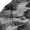
PLS-CADD was recently used on the design and construction of a 96-kilometer long, 230 kV, double circuit transmission line in Indonesia's remote Irian Jaya Province on the island of New Guinea. The line starts from a new power plant located on the southern coast of the island and extends through 27 kilometers of mangrove swamps, then through 40 kilometers of gently rising rain forest, and finally over 29 kilometers of extremely rugged mountainous terrain. The line is supported on tubular steel poles in the mangrove swamp and rain forest sections, and on latticed steel towers in the mountain section.
This was a fast-track project with an aggressive 21-month schedule for design and construction. XYZ point data from aerial topographic mapping was input to PLS-CADD, which was used to establish the alignment, structure locations and structure loadings. Loading reports from PLS-CADD were used to group the structures into 15 pole types and 6 tower types. Loading trees for each structure type were developed and incorporated into the structure design and fabrication specifications. The fabricators' consultants designed the structures using SPOLE for the tubular steel poles and TOWER for the latticed steel towers.
As more accurate ground survey data were obtained, it was input to PLS-CADD for final checks of the vertical and horizontal clearances. As a result of these checks, and in some cases due to foundation construction problems, it was necessary to make last minute changes to the structure locations in several of the line sections. The SPOLE and TOWER models of the structures were obtained from the fabricators' consultants and incorporated into the PLS-CADD models of these sections. This enabled us to immediately check the adequacy of the structures for the revised locations. Without this unique capability of PLS-CADD, the project schedule would have been impossible to achieve.
Have PLS-CADD Will Travel....
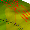
We had a project where the topography was such that precise structure placement was critical to the viability of the design. This was a relocation of 13 km of an existing lattice steel 287 kV transmission line in extremely rugged mountain terrain. Spans were up to 1000 metres in length and sidehill exceeded 50 deg in some locations. As photogrammetrically generated DTM data was not available, ground survey was necessary.
We loaded PLS-CADD onto a laptop and flew into the site area along with the survey crew.
The necessary surveyed ground data was able to be quickly loaded into the PLS-CADD model on site. Ground clearances and loads were then able to be checked immediately. Any necessary, or desired, changes could be identified and implemented without the delays associated with sending survey data back to the office, carrying out the design checks, then requesting survey changes from the field surveyors. This allowed for a very effective and efficient method of design in an area where time was short and access was difficult and expensive.
The flexibility of PLSCADD allows an unlimited combination of structures and line configurations to be quickly modeled. The engineer is limited only by the bounds of his creativity. Power Line Systems provides the tools to allow a competent transmission engineer to fully design and draft a project from start to finish.
I have been involved with the implementation and use of many computer aided design and drafting packages in the last fifteen years. These packages have included software produced by companies ranging from the small and obscure to the giant and well known. My company has primarily performed design of transportation infrastructure such as bridges and roads along with some electrical transmission tower design in the past. Up to now I was under the impression that it must be impossible to develop a complex design and drafting package without having many "bugs" and non-functioning features since all of the software I have been using seemed full of these.
Recently we began designing transmission facilities with PLSCADD. After a two day session with Steve Weber, we were up and running. I have yet to find a command that doesn't work, that hangs up my computer or requires spending hours on the phone with "support" personnel to find a "workaround". I have found the command structure of the software to be intuitive and the execution of commands to be flawless.
I highly recommend this software to anyone engaged in the design of electrical transmission facilities. It will save you time, aggravation and, most importantly, will allow you to optimize designs and save your client money.
Frank A. Polma, P.E.
Vice President of Operations
R-DELTA ENGINEERS, INC.
We have a situation on two of our major parallel 500 kV circuits. There is some significant soil movement affecting a couple of structures. Given the magnitude of the area in jeopardy, one of the possible courses of action is a relocation of both circuits.
With some high level photogrammetric ground data I was able to compile a model of the entire area with PLSCADD. With the DXF overlay feature, I could accurately establish existing structure positions in this ground model. I could then assess DOZENS of alternative alignments and come up with a solution that best utilized the existing structures and minimized exposure to future soil movements. Structure heights and loads were a mouse click away.
The entire exercise took me a morning!!!! Previous methods would have taken up to weeks to carry out.
Also...
I'm assembling close to 600 structure 'models'. We have an old existing 69 kV
transmission line that is a hodge podge of framing and guying configurations,
distribution underbuild, as well as pole height, class, and conditions. It is
routinely subjected to snow slides, rock slides, car/truck impacts, and heavy
ice and wind, etc. which explains the mixture of structures loadings. The
objective is to assess the structural capacity of the poles in preparation for
the addition of a fibre optics cable to the line. With minimal survey I can
quickly created a unique model for each structure with Wpole. The load of the
new fibre optics cable can be added and the structure analyzed. Any additional
guying or pole upgrade will be quickly determined.
The time for this analysis is SIGNIFICANTLY less than previous used methods.