Madison, WI 53719, U.S.A.
Phone: (608) 238-2171, Fax: (608) 238-9241
Email: info@powerlinesystems.com
|
|
5400 King James Way, Suite 300
Madison, WI 53719, U.S.A. Phone: (608) 238-2171, Fax: (608) 238-9241 Email: info@powerlinesystems.com |
| Home News Products |
Updated October 2015
This 2015 REA Crossarm Components Library is an update to the previous REA Crossarm Components Library and is a compilation of several documents. The dimensions and drilling guides came from the TCD drawings in the REA Bulletins 1728F-803, 1728F-804, 1728F-810, 1728F-811. The Type 01 - 05 are considered "distribution" crossarms. This component library is the same crossarm library used in our RUS example structure library.
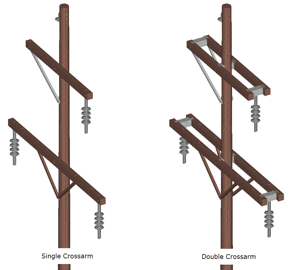
This library only contains single crossarm configurations. For a double crossarm it is recommended to model them separately with a spacer assembly that is modeled in PLS-POLE as another crossarm element.
The RUS Framing library contains examples of the double arms that can be used. These arms are modeled with the assumption that the maximum dimension of the crossarm is in the vertical direction except any
crossarm that may have a V suffix in the property label which is assumed oriented such that the short dimension is vertical.
Note: Some manufacturers may configure their double crossarms differently than the framing library which would of course necessitate the addition of these configurations and their associated properties in the framing library.
The crossarms in this library are assumed to be of Douglas Fir variety, with a Modulus of Elasticity of 1920 ksi, a Design Normal Stress of 7400 psi, and weight of 48 lbs/ft3. Again, these values should be adjusted by the engineer of record should other properties be required.
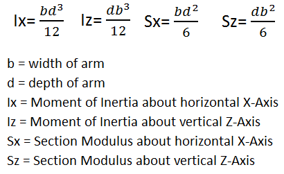
The crossarms in this library are based on the following equations; As the holes are not continuous along the entire arm, the Cross Sectional Area and Moment of Interia are based on the nominal dimensions of the crossarm without any bolt hole reductions.
As the point of maximum stress on any crossarm can occur at any location of either a planned or field drilled vertical bolt hole or a horizontal bolt hole,
the Section Modulus for the basic arms are based on a bolt hole being drilled in either direction.
As the holes are not continuous along the entire arm, the Cross Sectional Area and Moment of Interia are based on the nominal dimensions of the crossarm reduced by 1/8" due to notes at the bottom of the TCD drawings.
There is no deduction in the nominal dimensions for the Type 01, Type 02, Type 03, Type 04, Type 05, and Type 05M since a lesser cross-sectional dimension is not acceptable on the drawings. The bolt holes are added
at the joints along the arms according to the drawings since the point of maximum stress on any crossarm can occur at any location including that of planned or field drilled holes. The size of the bolt holes used
for these calculations comes from the TCD crossarm drawings in the RUS Bulletins and are automatically accounted for in the software by using the diameter of the bolt hole and the depth and width entered in the table.
The cross section area and section modulus of the arms will automatically account for these holes. The moment of inertia does not take into account a deduction for the bolt holes.
RUS Drawings used for hole placement and attachment points are W2.1G, W2.1G(M19), TCD-6, TCD-10, TCD-11, TCD-15, TCD-20, TCD-26, TCD-32, TCD-40, TCD-91, and TCD-92.
Note: RUS specifies a +/-1/8" tolerance on the dimensions thus the depth and width dimensions have been reduced by 1/8" in these calculations (see RUS 1724F-801 pages 96 - 101 and RUS 1724F-811 pages 105 - 133).
This in turn influences the cross section area, moment of inertia, and section modulus calculation for these crossarms. The distribution crossarms designate only a +1/8"tolerance on the dimensions so the depth and
width dimensions have not been reduced for these arms.
Click on REA Crossarm Components Library to download the library.
Joints on the crossarms were labeled with the following method
Suffix of H - Horizontal Hole at this joint
Suffix of V - Vertical Hole at this joint
For typical single pole arms where the attachment of the crossarm is on one pole the attachment joints on the arm are designated with a prefix of L or R to designate whether the joint is left or right of the attachment, then the distance in inches from the pole attachment, and then the suffix H or V to designate whether the attachment joint has a vertical or horizontal hole in the arm.
P - Typical Pole Attachment Point for single pole arm (Example PH means the pole attachment point that has a horizontal hole in the arm)
L45V - This would mean that there is an attachment joint that is 45 inches left of the pole attachment in the vertical direction
For multi-pole structure the arms may attach on more than one pole.
CP - Typical Center Pole Attachment Point on a multi-pole structure (CPH means the pole attachment point for the center pole of a multi-pole structure that has a horizontal hole in the arm)
LP - Typical Left Pole Attachment Point on a multi-pole structure
RP - Typical Right Pole Attachment Point on a multi-pole structure
SB - Split Bolt Location (Split Bolt is a bolt typically placed on an arm to keep it from splitting and may be next to a hole where a load would be applied in an opposite direction) (These are numbered left to right on the arm from the origin of the arm if there are multiple split bolts on an arm)
B - This the designation for a bracket attachment. These brackets may be for the creation of double arms or for swinging angle brackets. These are numbered similar to the split bolts in that they increase in number from left to right on the arm. For example B1H means this is the first hole on the arm used for some type of bracket attachment that has a horizontal hole in the arm.
LI, CI, RI - This is the designation for the approximate location for the left insulator, center insulator, and right insulator on the arm. This point could be where the actual insulator would attach or possibly where are bracket attaches for the insulator to hang from. You may see 2 insulator attachments for the same insulator location such as CI1V and CI2V. This would mean that something similar to a swinging angle bracket may attach to these joints where the center insulator would attach to this bracket. For example LIV would be a left insulator attachment with a vertical hole.
J - This is the designation for a jumper or idler string attachment. For example RIJV would represent the right insulator jumper attachment that has a vertical hole.
Example Calculation:
Type 12 - 8 arm with depth of 5-1/8 inches and width of 4-1/8 inches
Cross Section Area (in^2) = Depth * Width = (5.125 in - 0.125 in) * (4.125 in - 0.125 in) = 5 in * 4 in = 20 in^2
X Inertia (in^4) = Width * (Depth^3)/12 = (4.125 in - 0.125 in) * ((5.125 in - 0.125 in)^3)/12 = 4 in * ((5 in) ^3)/12 = 4 in * (125in^3)/12 = 41.66667 in^4
Z Inertia (in^4) = Width^3 * Depth/12 = (4.125 in - 0.125 in)^3 * (5.125 in - 0.125 in)/12 = (4in)^3 * 5 in/12 = 64in^3 * 5 in/ 12 = 26.66667 in^4
Weight (lbs) = Width * Depth * Length * Density = (4.125 in * 1 ft/ 12 in) * (5.125 in * 1 ft / 12 in) * 8 ft * 48lb/ft^3 = 56.375 lb
X Section Modulus (in^3) = Width *(Depth^2)/6 = (4.125 in - 0.125 in) * ((5.125 in - 0.125 in)^2)/6 = (4 in) * (25 in^2)/6 = 16.6667 in^3
Z Section Modulus (in^3) = Depth * (Width^2)/6 = (5.125 in - 0.125 in) * ((4.125 in - 0.125 in)^2)/6 = (5 in) * (16 in^2)/6 = 13.3333 in^3
Please note: Power Line Systems cannot provide a copy of REA bulletins, or any other standards or material for that matter, as these standards are copyrighted. We suggest RUS to download PDF copies of REA documents.
LEGAL DISCLAIMER: These files are being provided on an "as-is" basis. Power Line Systems, Inc. accepts no responsibility for the accuracy of the data herein, and the PLS-CADD end user is responsible for the use and verification of all data obtained in this library.