Madison, WI 53705, U.S.A.
Phone: (608) 238-2171, Fax: (608) 238-9241
Email: info@powline.com
| Home | Search | News | Products |

|
610 N. Whitney Way, Suite 160
Madison, WI 53705, U.S.A. Phone: (608) 238-2171, Fax: (608) 238-9241 Email: info@powline.com |
|||
|
The following technical note applies to TOWER versions 5 and 6.
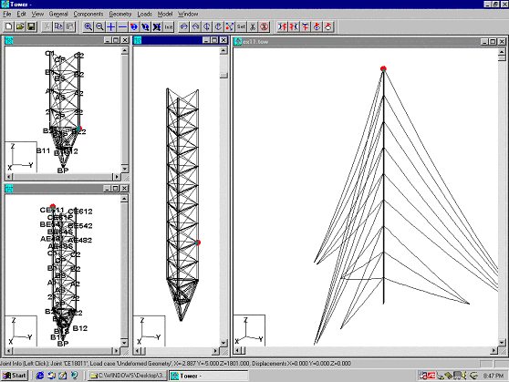
Example 11 shows how the model of a very tall tower can be generated rapidly from the model of one individual module. Except for the lower 40 foot portion of the tower which was developed manually and stored in the file "ex11base.tow" (shown in upper left corner of Fig. 7-5), the model of the entire 1800 foot mast (shown in the left pane of Fig. 7-5) was generated automatically in less than 10 minutes as described in this section.


With the function Geometry/Sections/Copy, we selected the upper 20 foot section (our basic module) at the top of the model of "ex11base.tow". This had the effect of storing that section as a template for the generation of the other modules. Then, with the function Geometry/ Sections/ Paste On Top, we repeatedly clicked on the top module to add a new section on top of that module. After the first click we got the model shown in the lower right pane of Fig. 7-5. After the second click, we got the model of the center pane. Finally, after 88 clicks, we had the entire mast at the right of Fig. 7-5 generated (more than 3000 members!).
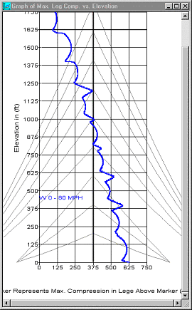
Then we attached the guys and linear appurtenances. We applied the design loads and ran an analysis, which took about one minute per load case with a 500 MHz processor machine. Based on the lower leg compression forces (see Fig. 7-6), we reduced the leg sizes from the base value of 6 1/4" SOLID ROUND down to 4" SOLID ROUND at the top. This is how we got the model of Example 11 (File ex11.tow). There was initially no effort in the development of the model of Example 11 to get a good design for the tension-only diagonals. In the following paragraph, we will describe how we got TOWER to automatically re-design all overloaded diagonals.
After running Example 11, we noted quite a few overloaded diagonal groups (displayed in red if you load the model and analyze it in TOWER). Using Model/Auto-Fix Angles, all overloaded diagonals were redesigned automatically. This optimum re-design and the associated re-analysis took less than 3 minutes.
Instead of using Model/Auto-Fix Angles, we could have used Model/Interactive Member Sizing to manually select members to be re-designed. Either command can be used to upgrade existing towers for which design criteria or loadings are changed.