PLS-POLE
Analysis and Design of Structures with Wood, Laminated Wood, Steel, Concrete and FRP Poles or Modular Aluminum Masts
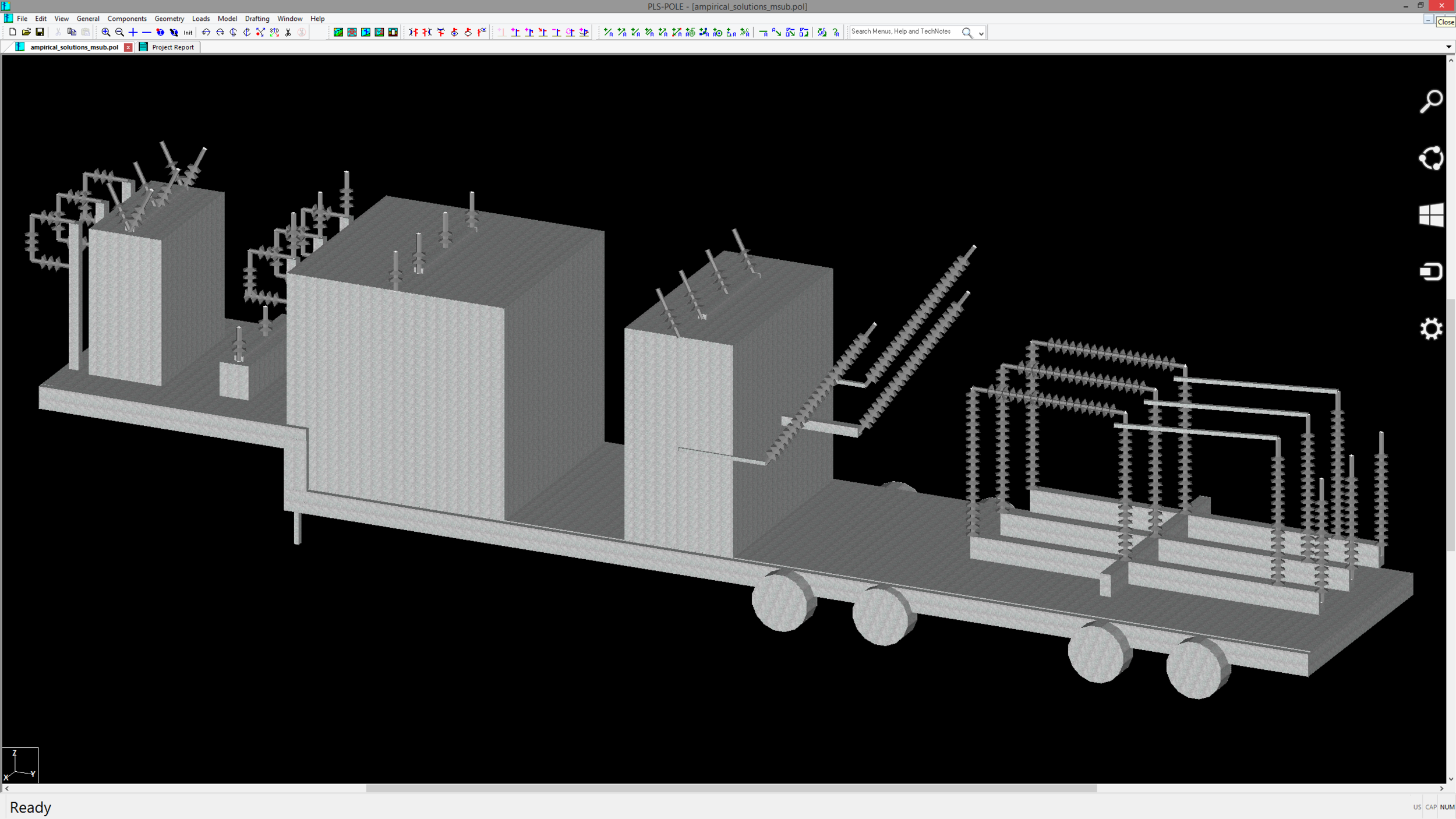
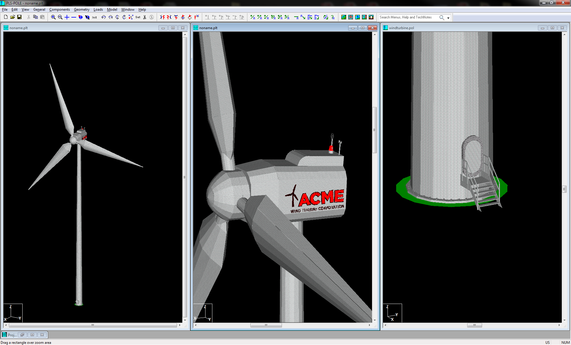
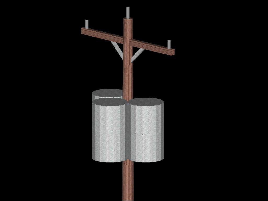
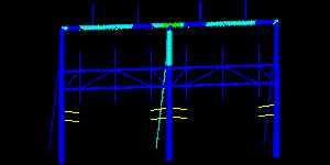
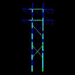
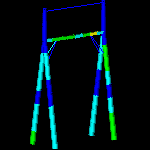
PLS-POLE is a powerful and easy to use Microsoft Windows program for the analysis and design of structures made up of wood, laminated wood, steel, concrete and Fiber Reinforced Polymer (FRP) poles or modular aluminum masts. The program performs design checks of structures under user specified loads and can also calculate maximum allowable wind and weight spans. Virtually any transmission, substation or communications structure can be modeled, including poles, H-frames, A-Frames, and X-Frames. These models are rapidly built from components such as poles, arms, guys, braces, and insulators.
PLS-POLE is the result of nearly 25 years of evolution from our earliest structural analysis programs. It is the direct successor of our popular CPOLE, CFRAME, SPOLE, SFRAME, WPOLE, WFRAME and G-MAST programs. During our years supporting these programs we have continually refined our algorithms, user interface and program design. The result is PLS-POLE, a powerful and comprehensive design tool with unsurpassed reliability and ease of use.
Comprehensive Structure Modeling
PLS-POLE structures are collections of the following elements:
Concrete poles
Steel poles
Wood poles
Laminated wood poles
Fiber Reinforced Polymer (FRP)
Modular latticed masts
Davit arms
Cross arms
Guys
Cables
Braces
Equipment (user defined items like transformers, ladders...)
Insulators (clamp, strain, post, suspension, 2-parts)
Building a structure is as simple as selecting the desired element from a library of available elements and telling the program where it attaches to other elements. You are free to mix and match the various elements at will. This gives you the power to create arbitrarily complex structures and even allows you to mix wood, steel and concrete elements in the same structure.
The element libraries define the sizes, weights and strengths of your standard structural components. You can create these libraries yourself or use libraries provided by your suppliers. Using libraries of standard reusable components greatly enhances your productivity by significantly reducing the amount of input, which also reduces the chance of error.


Simple and Powerful Finite Element Analysis
PLS-POLE takes the pain out of finite element analysis. An H-Frame in PLS-POLE is input as a collection of macro elements like poles, cross-arms and braces. These elements are selected from a library where you enter the properties of macro elements like a pole's top and base diameter, wall thickness and shape (round, 16 sided…). PLS-POLE automatically breaks your macro elements down into many cable, truss and beam elements. In just a few minutes with PLS-POLE you can build structures that would take days to model in a traditional finite element program.
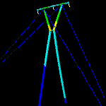
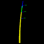
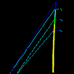
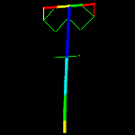
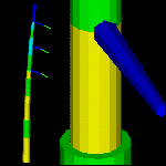
2-Part insulator going into compression A special version of our SAPS finite element analysis engine powers PLS-POLE. We designed SAPS specifically for solving complicated transmission line and guyed communication structure problems that other finite element programs couldn't. For nearly 30 years of production use SAPS has proven to have one of the best nonlinear cable elements available anywhere.
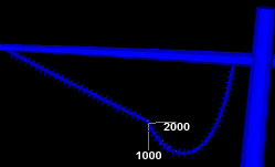
PLS-POLE is capable of performing both linear and nonlinear analyses. Nonlinear analysis allows you to see P-Delta effects, to detect instabilities, and to perform accurate buckling checks. PLS-POLE models guys, cables and 2-part insulators as 3-d cable elements. This sophisticated analysis works even when elements have large displacements as is the case with the 2-part insulator pictured to the right.
ASCE and Other Code Checks
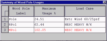
Once PLS-POLE has calculated the forces and moments experienced in the different pieces of your structure it compares them against code capacities. The results of these checks can be displayed in text reports, spreadsheets or color-coded graphics.
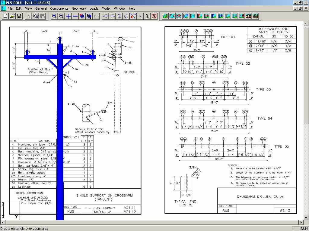
Either ASCE/SEI 48-11 (previously ASCE manual 72) or other international standards can be used to check steel poles and tubular steel elements. Wood poles are checked against their ultimate stress and the fiber stress can be reduced with height according to ANSI O5.1 (2002, 2008, 2015, 2017). PLS-POLE detects wood pole buckling by your choice of exact nonlinear analysis, the Gere and Carter method, the REA method or a user programmable method. Concrete poles are checked against a moment capacity diagram. The PLS-POLE manual describes how these checks are implemented and lists the assumptions made.
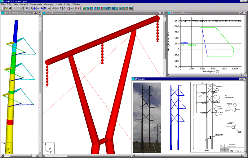
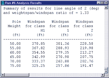
Text summary of allowable spans for different heights and classes of wood poles In addition to these code checks PLS-POLE can calculate pairs of allowable wind and weight spans for a specified value of their ratio, or better yet, determine entire interaction diagrams between the allowable wind and weight spans. Optimum spotting performed with these interaction diagrams will result in a more economical solution than traditional spotting where a single wind and weight span pair is used.
Intuitive Graphical User Interface
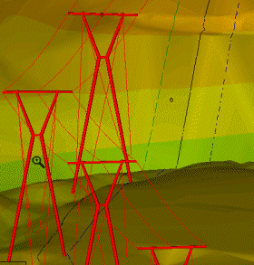
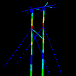
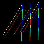
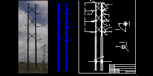
PLS-POLE makes extensive use of 3-d graphics to help you visualize your structure. We draw all elements as accurately as possible and let you view the structure from any direction making modeling mistakes immediately apparent. If you see a mistake you simply click on it to edit the problem element.
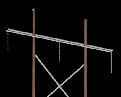
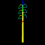
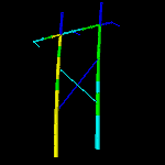
Close-up of frame showing double cross arm and insulators After an analysis, elements are color-coded based on their utilization with overstressed elements graphically shown in red. Of course, these elements can be edited with a single click. Overstressed elements are also colored red in text and spreadsheet reports.
Just as important as the graphical feedback are the many sanity checks PLS-POLE makes on your input data. In the course of reviewing thousands of problematic structure models we have identified many common modeling errors. PLS-POLE automatically detects these errors and flags questionable input to save you time.
Interoperability
While PLS-POLE is a stand-alone program it's open design allows it to easily interface with other programs.
PLS-POLE provides a well defined XML output file and hooks that enable pre and post-processors to be connected to the program making it the ideal engine of your custom pole process.
PLS-POLE can read files from our CPOLE, CFRAME, SPOLE, SFRAME, WPOLE, WFRAME and G-MAST programs. We recognize the investment our clients have in structure models created in these programs and have made backwards compatibility a high priority. If you are a user of these earlier programs please see the PLS-POLE page on our web site for a more detailed list of improvements made in PLS-POLE.
PLS-POLE structures used in PLS-CADD Users of our PLS-CADD line design program can use PLS-POLE to prepare allowable wind and weight span or interaction diagram files for optimum spotting. They can also take PLS-POLE structures and spot them in a line. PLS-CADD can calculate the loading on a structure at a particular location and display the results of a PLS-POLE check with those loads.
PLS-POLE results are presented in a combination of graphical views, spreadsheet views and text reports. All of this information can easily be exported to other programs. Graphical results can be saved in DXF files compatible with most CAD systems. Spreadsheet results may be pasted into spreadsheet programs, exported to ODBC compliant databases or saved to an XML file. Text results can be customized by the user and saved to files or pasted into word processing programs.
Summary
PLS-POLE provides all of the capabilities a structural engineer requires to design transmission, substation or communications structures. It does so using a simple easy to use graphical interface that rests upon our time tested finite element engine. Regardless of whether you want to model a simple wood pole or a guyed steel X-Frame; PLS-POLE can handle the job simply, reliably and efficiently.
If you would like more information about PLS-POLE please contact us.
Summary of Features
A Microsoft Windows 10 or 11 (x64) environment that lets you:
Specialized program for the analysis and design of transmission, distribution and substation structures made up of wood, laminated wood, FRP, steel and concrete poles or modular aluminum masts. (single poles, H-Frames, A-Frames, X-Frames…)
Structures are made of standard reusable components that are available in libraries. You can easily create your own libraries or get them from a manufacturer
Structure models are built interactively using interactive menus and graphical commands
Automatic generation of underlying finite element model of structure
Linear and Nonlinear finite element analysis options
Implements the 2017 edition of ANSI O5.1 including reduction of fiber stress with height
Wood poles can be selected from ANSI O.5 standard
Steel poles can have circular, 4, 6, 8, 12, 16, or 18-sided, regular, elliptical or user input cross sections (flat-to-flat or tip-to-tip orientations)
Base plate analysis and design for steel poles
Steel and concrete poles can be selected from standard sizes available from manufacturers
Automatic pole class selection
Steel pole shaft optimizer that considers stresses and allowable deflections
Cross brace position optimizer
Capability to specify pole ground line rotations
Capability to model foundation displacements
Can optionally model foundation stiffness
Guys are easily handled (modeled as exact cable elements in nonlinear analysis)
Automatic distribution of loads in 2-part suspension insulators (v-strings, horizontal vees, etc.)
Design checks for ASCE, AS/NZS 7000 or other requirements
Automatic calculation of dead and wind loads
Automated loading on structure (wind, ice and drag coefficients) according to:
ASCE 74-1991, 2009
NESC 2002, 2007, 2012, 2017
IEC 60826:2003
IS 802 : 1995, 2015
EN50341-1:2001 and 2012 (CENELEC)
EN50341-3-2:2001 (Belgium NNA)
EN50341-3-9:2001, EN50341-2-9:2015, 2017 (UK NNA)
EN50341-3-17:2001 (Portugal NNA)
AS/NZS 7000:2010
ESAA C(b)1-2003 (Austalia)
TPNZ (New Zealand)
REE (Spain)
Russian 7th
ISEC-NCR-83
Detects buckling by nonlinear analysis
Easy to interpret text, spreadsheet and graphics design summaries
Automatic determination of allowable wind and weight spans
Automatic determination of interaction diagrams between allowable wind and weight spans
Automatic tracking of part numbers and costs
Detailed user's manual with examples
On-line/electronic user's manual linked in to provide context sensitive help (also available in French)
User interface available in English, French and Spanish
US or SI (metric) units
Powerful graphics module (members color-coded by stress usage)
Graphical selection of joints and components allows graphical editing and checking
Poles can be shown as lines, wire frames or can be rendered as 3-d polygon surfaces
CAD design drawings, title blocks, drawing borders or photos can be tied to structure model
Can link directly to line design program PLS-CADD
Automatic generation of structure files for PLS-CADD
Links
Technical Notes: You can find many technical notes here which discuss topics such as available loading methods, applying NESC insulator requirements, importing and exporting data, weight spans, customization and localization, etc.
Videos
Joint use example in PLS-CADD/Lite and PLS-POLE (demonstrates new wizard interface)
PLS-CADD customize structure command for moving structure attachments and guy anchors with PLS-POLE structures
Information for Prospective Clients
Frequently Asked Questions Regarding the Purchase of PLS Software
Miscellaneous
Example Structures
Sample Steel Poles
Sample Steel Frames

PLS-POLE Hall of Fame