Madison, WI 53705, U.S.A.
Phone: (608) 238-2171, Fax: (608) 238-9241
Email: info@powline.com
| Home | Search | News | Products |

|
610 N. Whitney Way, Suite 160
Madison, WI 53705, U.S.A. Phone: (608) 238-2171, Fax: (608) 238-9241 Email: info@powline.com |
|||
|
With the release of PLS-CADD 5.09 and SAPS 5.24, the procedure below is obsolete. You can now display a finite element or multi-span sag-tension result in PLS-CADD by simply selecting the weather case you want and picking the wire condition "FE Initial", "FE Creep" or "FE Load". For more information on finite element sag-tension integration please see Working With Finite Element Multi-Span Sag-Tension in PLS-CADD While the procedure has changed in the new versions the result is similar to what is shown below and the reasons for wanting to do it have not changed.
All calculations done within PLS-CADD use ruling span based sag-tension. However, it is ocasionally necessary to use a more sophisticated finite element based sag tension calculation. Situations where this may be required include large span length variations, very steep terrain, unbalanced ice, broken conductors, marker balls, heavy dead end strings, mid-span loads, and slack adjustments. Our SAGSEC and SAPS programs use finite element based sag-tension and were developed with these types of problems in mind.
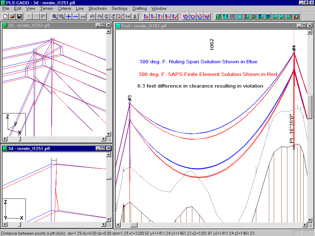
Many clients have expressed a desire to perform multi-span sag-tension on their PLS-CADD models. Responding to this need we added new functions to PLS-CADD which export a line model to SAPS or SAGSEC and allow you to superpose their results in the PLS-CADD profile and 3d views. The figure below shows a comparison of PLS-CADD and SAPS results for a 300 degree F. case. The PLS-CADD results are shown in blue and the SAPS results are shown in red. In this particular example the multi-span sag-tension calculation results in 6.3 ft. more sag than the ruling span calculation revealing a significant clearance violation. The view in the lower left portion of the screen shows the frame deflecting more than 1 foot in the longitudinal direction. In this case the clearance difference is due to the large changes in the end elevations and span lengths of adjacent spans. For more information about the limitations of ruling span methods see "Limitations of the Ruling Span Method for Overhead Line Conductors at High Temperatures" presented at the IEEE 1998 Winter Power Meeting by the "Bare Conductor Sag at High Temperature" task force.

Procedure for integrating SAPS or SAGSEC graphics within PLS-CADD:
Note: Portions of the procedure below rely on features introduced in PLS-CADD 4.67, SAPS 5.09 and SAGSEC 4.09
Upon completion of this procedure you should see the graphical results from SAPS or SAGSEC superposed over the PLS-CADD graphics in the 3D and profile views. You can control the display of the SAPS/SAGSEC geometry through the "SAPS-SAGSEC Geometry Display Options" which is located in either the File/Export or the Drafting/Attachments menu depending on your PLS-CADD version.