Madison, WI 53719, U.S.A.
Phone: (608) 238-2171, Fax: (608) 238-9241
Email: info@powerlinesystems.com
|
|
5400 King James Way, Suite 300
Madison, WI 53719, U.S.A. Phone: (608) 238-2171, Fax: (608) 238-9241 Email: info@powerlinesystems.com |
| Home News Products |
PLS-POLE allows line designers to easily develop their own structures according to their own specifications.
The Rural Utilities Service (RUS) of the United States Department of Agriculture (USDA) has developed structure specifications and framings for many structures from distribution voltage levels through 230 kV that many engineers use either directly, or with modifications, for their line design needs.
To make using RUS structure specifications and framings easy, Power Line Systems has developed PLS-POLE models and a Framing library of these standard framings. They MUST be reviewed by a competent engineer familiar with their structure standards to ensure that the RUS models follow company specific requirements, and modifications be made therein to meet such requirements. (As a PLS-POLE user, you should be familiar with how easy it is to change things to meet your own requirements in PLS-POLE.) We recommend that these changes be made to the “seed structures” provided below, and then you may simply use the Batch Save command under the File menu in PLS-POLE to create a family of pole heights and classes for each company's standard libraries and/or specific projects. You can also use the Components/ Framing/ Import Other Models command to import other standard framings into the library. These files are provided as examples that must be reviewed by the engineer of record to verify and confirm all inputs. If you would like to make any changes to the assumptions in the model including items like component libraries or strength checks you can use the File/Batch Modify command to quickly modify all structures in the structure library. You can also use the Components/ Framing/ Update Component Library to make these changes to the framing library. Click here to see a video demonstrating the use of the Framing Manager
Click here to download a bak file containing all of these RUS PLS-POLE Models. These models require PLS-POLE version 14.00 or newer.
Click here to download a framing library file containing all of these RUS Framings. This framing library requires PLS-POLE version 14.00 or newer.
Click here to download a framing library file containing all of these RUS Framings, tailored for distribution use. This framing library requires PLS-POLE version 14.00 or newer.
October 2015: Updated to use new crossarm library and framing library available.
September 2013: Updated to use new REA crossarms component library.
February 2013: Added new structure voltages 24.9/14.4 KV, 34 KV, and 46 KV.
January 2013: Now use more conservative calculation of double crossarm capacity as detailed in the notes section of the component file.
November 2012: Chained insulators modeled in a manner that is compatible with PLS-CADD 12.30.
June 2012: Now use ANSI O5.1.2008 strength check for wood poles.
Click here to see a schedule of the structures that are available in the .bak file
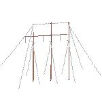
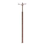
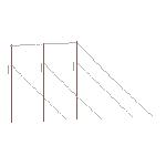
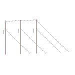
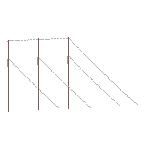
All wooden structure models were taken from RUS Bulletins 1728F-810 Electric Transmission Specifications and Drawings, 34.5kV Through 69kV, 1728F-811 Electric Transmission Specifications and Drawings, 115kV Through 230kV, and 1728F-803 Specifications and Drawings for 24.9/14.4 kV Line Construction. While these structures may not be an exhaustive list of all structures available in the bulletins they contain many of the structure types that can be used as a guide to create your own user defined structure models. These bulletins can be found at https://www.rd.usda.gov/publications/regulations-guidelines/bulletins/electric
Below is a list of each component library and the items associated with it.
Wood Pole Material - ansi_2008.mat - All wood poles are modeled with SP-Southern Pine with a Modulus of Elasticity of 1800 ksi, Design Stress MOR of 8 ksi, and a weight density of 60 lbs/ft^3. The wood pole strength check for all poles is set to ANSI O5.1.2015 under the General/General Data dialog in the models. The wood pole stress usage will be determined for all elements making up each pole with the strength varying along the pole according to this ANSI standard. If you do not want to use this strength check you can use the File/Batch Modify command to change the strength check for selected models. You may also change the wood pole material selected using this Batch Modify command if something other than Southern Pine is used.
Wood Poles - sp-ansi.wpp- The embedment depth for all poles in this library is 10% of the pole height plus 2’. So for example a 100’ pole will be embedded 12' in the ground. If another embedment depth is required, the engineer will need to change this depth in the pole model with % and constant override in the Geometry/Wood Poles table.
Steel Poles - default steel pole.spp - The embedment depth for all poles in this library is 10% of the pole height plus 2'. So for example a 100’ pole will be embedded 12’ in the ground. If another embedment depth is required, the engineer will need to change this depth in the pole model with % and constant override in the Geometry/Steel Poles table.
Braces - brace.brc- Brace geometric data is assumed from typical brace usage on the RUS drawings. All braces for each structure should be reviewed by the engineer to verify the company’s standard brace is being used. The engineer should verify all calculations for these braces. Please note that the modulus of elasticity is 1600 ksi, the design normal stress is 7400 psi, the density of 48 lb/ft^3 is taken from Douglas Fir.
Cables - guy.cab- All models are built with either 7/16” or 3/8" High Strength 7 Strand Steel wire. However, other cables are available in the library. In this library there are stock numbers assigned to some of the items. By placing a stock number in this column it will automatically pull these items from the parts library when populating a material list in PLS-CADD.
There are four types of cables that are available from the model for the 69 KV and above models. They are as follows:
TG-_1A – This is a single guy from the pole to a single anchor rod.
TG-_1B – This is a double guy from the pole to a single anchor rod.
TG-_1C – This is a double guy from the pole to a double anchor rod. Please note that it is assumed in this model that a split guy in this configuration has the same strength as a double guy. To more accurately model a split guy two TG-_1A type guys should be used. The model will render a split guy in the TG-_1C as a single cable that should be snapped to the midpoint between the two anchor rods if this method is chosen.
TG-_1D – This is a tie guy from one pole to another pole.
Davit Arms - default-davit.dvt - We not only use these for davit arms, but also for connecting crossarms and bayonets.
Tubular Steel Davit Arms - default steel davit.tdv
Crossarms - crossarm_2015.xrm - Crossarm geometric data is taken from the RUS bulletins 1728F-810 Electric Transmission Specifications and Drawings, 34.5kV Through 69kV, 1728F-811 Electric Transmission Specifications and Drawings, 115kV Through 230kV, and 1728F-803 Specifications and Drawings for 24.9/14.4 kV Line Construction. These bulletins can be found at https://www.rd.usda.gov/publications/regulations-guidelines/bulletins/electric. The crossarm data is found on the TCD drawings. Bolt holes are entered from the TCD drawings as attachment points for the crossarm and to account for the loss in strength and cross-sectional area. All crossarms for each structure should be reviewed by the engineer to verify the company's standard crossarm is being used. The engineer should verify all calculations for these arms. Please note that the modulus of elasticity is 1920 ksi, the design normal stress is 7400 psi, and the density is 48 lb/ft^3. Double crossarm are modeled individually on the face of the pole with double arming bolts or assemblies. All strengths must be verified by the engineer of record.
Tubular Steel Crossarms - tubular crossarm library.xtm
Equipment - equipment.eqp - A generic transformer is used on some of the distribution models. The physical properties of the transformer should be verified by the engineer of record as the one provided in the library is for demonstration purposes only.
Insulators - insulator.inl - All insulator strengths are factored such that the structure loads in the criteria file should be set up to NOT reduce the strength of the insulators unless the company wishes to use a strength factor besides 0.5. For example if the engineer wishes to use a 0.4 factor on the insulators then they should place a 0.8 strength factor in the PLS-CADD structure loads within the criteria file. Compression strength must be verified for the pin and post insulators as they have been set to an arbitrarily low strength.
Clamp – One clamp is provided in the library which is called Fict and has a holding capacity of 10000 lbs.
Strain Properties – Strain insulators on deadends are labeled as follows:
TM-4E – This is the strain clamp associated with overhead ground wires. This has a tension capacity assumed of 18000 lbs.
TM-1D-___ - This is the deadend associated with the phase conductors and will use the appropriate voltage suffix. For example, a TM-1D-69 is the deadend assembly associated with a 69kV phase.
Suspension Properties - All suspension insulator assemblies are calculated with a length including a Y-ball connection. Suspension Insulators are labeled as follows:
TM-4A – This is the suspension assembly associated with the overhead ground wire. It has an assumed tension capacity of 16000 lbs.
TM-1B-___ - This is the suspension assembly associated with the phase conductors and will be ended with the appropriate voltage suffix. Such that a TM-1B-69 is a suspension assembly associated with a 69kV phase. Please note that all TM-1B assemblies are modeled with 20 kip insulators.
TM-1C-___ - This is the suspension assembly associated with the phase conductors and will use the appropriate voltage suffix. These are for angle structures such that they have one extra bell in the assembly. Please note that all TM-1C assemblies are modeled with 30 kip insulators.
Insulators used in lower voltage structures are considered part of the structure frameset. All inputs MUST be verified by engineer of record.
Post Properties – All horizontal post insulators usedin the model are assumed to be trunion type connection with a gain base from the Rodurflex properties available for download in the Lapp insulator library. The strength curves of these posts are based on the RCL values. A note is included at the top of the components file that details which insulators are being used in the model. The engineer must verify that these post insulators meet their company’s criteria. The Rodurflex catalog is available at https://www.lappinsulators.com/products/composite-insulators/rodurflex-line-post-insulators/?L=2
Note that vertical post insulators have modified strength curves that allow values in both the negative and positive vertical directions such that it would allow uplift if the post were in a horizontal position. However, when the post is placed in a vertical position this allows for the post to have transverse capacity equal to the vertical capacity of the post. Any questions regarding post strengths should be directed to the insulator suppliers' technical representatives. All distribution pins strength must be verified by the engineer of record.
Swing Angle Calculations All swing angle calculations are based on RUS Bulletin 1724E-200 under Chapter 7. This bulletin can be found at https://www.rd.usda.gov/publications/regulations-guidelines/bulletins/electric Please note that there are 4 swing cases available in the model. Swing Case 1 is the no wind case, Swing Case 2 is the moderate wind case for tangent structures, Swing Case 3 is the high wind case, and Swing Case 4 is the moderate wind case for angle structures. Please note that 6 inches of extra clearance have been added to the no wind clearance per Note A on Table 7-1 for the angle structures since these structures have 5 insulators.
Also note that these swing calculations are based on the bottom 0.4 feet of the insulator string being energized to take into account the suspension clamp and necessary connection hardware. The engineer should verify this meets a company's standard for swing clearances.
The distribution swing angles must be verified by the engineer of record to meet company requirements
Angle Brackets All angle brackets are modeled as 2-part insulators under the Geometry/Insulators/2-Part menu. All lengths of these angle brackets were taken from the RUS standard drawings. The engineer should verify these lengths correspond with the company's standard angle brackets. The 2 part insulators were assigned a set and phase to allow for chaining of suspension insulators that allow for appropriate longitudinal movement of the swinging angle bracket. In order for this to be taken into account the selection to include chained insulators must be selected in PLS-CADD under the Criteria/ SAPS Finite Element Sag Tension dialog.
Running Corner Connections All running corner connections typical of a TH-4 or TS-4 are modeled at 3 inches from the face of the pole to take into account the hardware connection at the pole face.
Crossarm Insulator Attachment All insulator attachments below the crossarm are modeled at 1-5/8" below the arm. This is to take into account a shoulder eyebolt below the arm less half the pin diameter of a Y-Clevis Ball or for the double arm assembly.
Wood Pole Bolt Holes and Crossarm Bolt Holes Bolt holes are included in the component libraries for the crossarms and in the attachment geometry for the wood poles. Bolt holes for the crossarms were taken from the TCD drilling guide drawings for crossarms in the RUS bulletins. Bolt holes were also assumed for the wood poles and must be verified for the structure models and the framing library to make sure they meet company standards.
Structure Phasing (Insulator Link) For transmission voltages all conductor phases are Set 5. With the left phase being Phase 1, center phase being Phase 2, and the right phase being Phase 3 on horizontal construction structures. If there are two overhead ground wires (OHGW) then the left OHGW will be set 1 phase 1 and the right OHGW will be set 2 phase 1. A deadend structure follows the same principle for the ahead sets but the back sets will be identified by set 15 for the conductors, set 11 for the left OHGW, and set 12 for the right OHGW. Any jumper strings attached to the structure are identified as set 60 with similar phasing. For the distribution voltages sets 21 through 26 are used for the phase conductors and sets 27 through 30 are used for the neutral conductors. A deadend structure follows the same principle for the ahead sets but the back sets will be idenitified with a set number that is 10 higher so the back sets for the phases will be 31 through 36 and for the neutral it will be sets 37 through 40. The phasing follows the same rules above for horizontal construction on transmission structures.
A vertical construction single pole has all conductor phases as Set 5 for transmission voltages. The center phase is at the top of the pole as Phase 2, the left phase is the middle phase as Phase 1, and the right phase is at the bottom of the pole as Phase 3. The OHGW is identified as set 1 phase 1 on these structures. A deadend structure follows the same principle for the ahead sets but the back sets will be identified by set 15 for the conductors and set 11 for the OHGW. Any jumper strings or posts are attached to the structure and identified as set 60 with similar phasing. The same rules are used for phasing in the distribution voltages as well.
The file available for download is the RUS_Structures.bak. The first step in the process is to restore the backup file to a folder and review all strength and modeling assumptions to ensure they are correct and meet your company's standards. The next step is to decide how the designer wishes to use the structures in relation to a particular project. There are two main choices for the structures' location. One is to locate all structure files and component files within a standard directory that the designers can pull structures from to populate a particular model. The other is to locate all structure files and component files within a project directory that designers have access to not only populate the PLS-CADD model, but also have the ability to change components and modeling assumptions within PLS-POLE without changing the properties for all previous projects using these structures. For the example below we will restore to a computer hard drive in which the designer can review the strength and modeling assumptions and then take the step of making a backup file with any changes for distribution to project folders or to a standards folder on the network.
In PLS-POLE use File/Restore Backup and select the rus_structures.bak file that you saved from the PLS website. Select Open and then answer Yes when prompted to Ask for permission before overwriting existing files. You will then enter the Directory Mapping for Restore dialog box (Fig 1.1) which has 7 rows of data to be restored to 7 different file folders. Row 1 is the Component data used by PLS-POLE. Rows 2 through 6 are the structures for different voltage levels 230kv, 161kv, 138kv, 115kv, and 69 kv respectively. Row 7 is the standard folder which contains the blank pole files that were used for constructing the structure models. You will notice that they are already mapped to the C:\rus structures folder. If you wish to restore to another folder then you should select the appropriate directory for each of these files by picking Select Directory in the third column of each row and then selecting the correct storage folder for each item. We recommended that you keep the same folder names for each of the rows so that the structures will be kept separated by their voltage classifications.
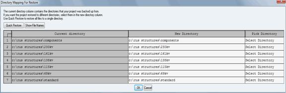
Figure 1.1
Once you select OK the program will restore all models to the appropriate folders and the then prompt you to open the bayonet standard.pol file which is a blank pole file with a bayonet already modeled. Select No in this dialog box. You will then be able to open any of the pole models to review the components and modeling assumptions using theFile/Open command.
Once you have reviewed and verified the models and made any changes necessary to comply with your particular strength requirements and standards you can make a backup of these structures for use in a specific project or to restore to a company standards directory. In order to make a backup file with multiple pole models open any pole model you wish to include in the backup and use File/Backup to name the backup file. For our purposes we will name the file CompanyA-RUS-Structures.bak and save it to a folder of your choice (Fig. 1.2).
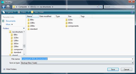
Figure 1.2
Click Save at the bottom of the dialog box and you will be prompted with the Backup Options dialog box (Fig. 1.3). In this box check all boxes except for the Transmit backup file to PLS for technical support. By checking the Prompt to include additional models in backup you will be able to add additional structures to this backup file.
Figure 1.3
After selecting OK you will be given the opportunity to select additional models to include in the backup. You can select individual models one model at a time or all models within a folder by using the CTRL or SHIFT keys in conjunction with a left click of the mouse (Fig. 1.4). Once you select models within a folder and select Open you will be in the File Backup Additional Models dialog box (Fig. 1.5) where you can select to add more models from a different folder by clicking Yes or to continue with the backup by selecting No. If you are done adding models you will select No and then the program will tell you exactly how many files were backed up in relation to the selections made.
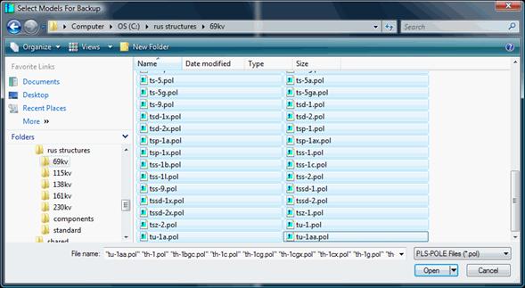
Figure 1.4
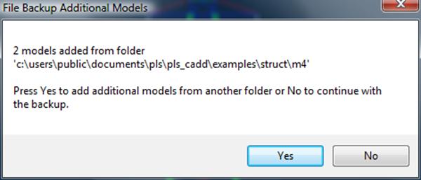
Figure 1.5
To restore these models to another directory follow the same process as mentioned above.
Once these seed files have been saved to a particular folder whether it be on the network in a standards folder or in a project specific folder you will want to save a range of structure heights and classes for use in the PLS-CADD model. The File/Batch Save command in PLS-POLE will allow you to quickly and easily save a range of heights and classes of poles while keeping the same pole top geometry.
To Batch Save a pole model, open the particular seed model in PLS-POLE. For example let's save a variety of pole heights and classes for the TS-1 frameset in the 69 KV folder. After opening the model in PLS-POLD, use File/Batch Save. The Filter By Length and Class dialog box (Fig. 1.6) opens and you can pick the various lengths and classes you wish to save for the TS-1 structure model. For our example let's only save poles from 50 to 90 feet from Class 3 to Class H1. Just choose these parameters in the dialog box and each of the options will highlight when selected. To deselect one of the options just click on it again and it will no longer be highlighted. After choosing these options click OK.
Figure 1.6
The Batch Save dialog box (Fig. 1.7) then appears with the pole heights and classes you selected highlighted on the left side of the box. On the right side of the box there is a edit field with ts-1-%C.%L. This dictates the naming convention of the structure file. So in this example a 50 foot Class3 TS-1 structure will have the filename ts-1-3-050.pol. A button beneath this data entry box is for selecting the destination folder for these structures. By selecting this box you may choose which folder you wish to save all the structure class and height variation models in. You can also choose to have them created with or without the .pol extension by checking the box at the bottom right of the dialog box. Then select OK and PLS-POLE will create the different models associated with these classes and heights. The pole variation files are shown in the window of Fig. 1.8.
Figure 1.7
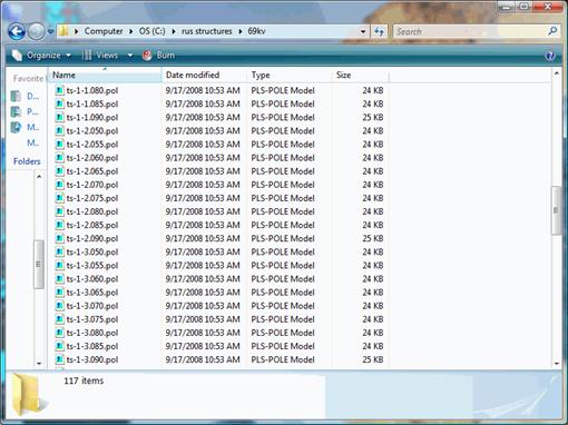
Figure 1.8
Once you have selected the method by which you wish to store your structures and made the different height and class models in PLS-POLE you can then begin using them within PLS-CADD. Once you have a PLS-CADD file open you can use File/Preferences to change the Setting for Project on the Structure Directory to the folder where you batch saved the different height and class configurations and also change the Setting for Project on the Part/Assembly Library to the part-and-assembly.prt file in the component folder where you restored the structure files (Fig. 1.9). Once this is done you can select OK at the bottom of the dialog box.
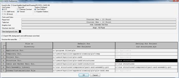
Figure 1.9
Now in PLS-CADD when you select Structure/Add it will automatically open in the folder identified in File/Preferences and you can easily add structures from the library you have created. By mapping to the correct part and assembly file it will also enable automatic generation of structure material components.
LEGAL DISCLAIMER: These files are being provided on an "as-is" basis. Power Line Systems, Inc. accepts no responsibility for the accuracy of the data herein, and the PLS-CADD end user is responsible for the use and verification of all data obtained in this library.
A schedule of each structure is listed below showing the voltage and family folder in which it can be found.
 VA1.11
 VA1.11P
 VA1.1P
VC1.11 with Transformer VC1.11L
 VC1.11P
 VC1.41
VC1.41P VC1.81G
 VC2.52
 VC2.52P
VC5.71L-10ft VC5.71L-8ft
 VC5.82G
 VC6.21
TP-1-34 TP-1A-34
 TP-3-34
 TP-34B1
TP-34GB1 TP-34GB2
 TP-34GC
 TP-3A-34
TP-5-34 TP-5A-34
 TP-7-34
 TPD-1-34
TP-1-46 TP-1A-46
 TP-3-46
 TP-3A-46
TP-46G TP-46GB1
 TP-46GB2
 TP-46GC
TP-5-46 TP-5A-46
 TP-7-46
 TPD-1-46
TH-4G TH-5-11.5
 TH-5-12.5
 TH-5-12
TH-5-13.5 TH-5-14.5
 TH-5D
TH-5D TH-5G-11.5
TH-5G-12 TH-5G-13
 TH-5G-14
 TH-5G-15
TP-69C TP-69G
 TP-69GB1
 TP-69GB2
TH-3AA TH-4A
TH-4A TH-4AA
 TH-5A-13.5
TH-5A-14.5 TH-5A-15.5
 TH-5A-16.5
 TH-5A-18
TH-5AA-13.5 TH-5AA-14.5
 TH-5AA-15.5
 TH-5AA-16.5
TP-115B1 TP-115B2
 TP-115C
 TS-3A-115
TS-3AA-115 TS-4A-115
 TS-5A-115
 TS-5AA-115
TS-115 TS-115A
 TS-115B
 TU-1-115
TH-10 TH-10V4
 TH-10V4X
 TH-10V4XX
TH-10VI TH-10VIX
 TH-10VIXX
 TH-10VO
TH-10VOX TH-10VOXX
 TH-10X
 TH-10XX
TH-11 TH-11V4
 TH-11V4X
 TH-11V4XX
TH-11VI TH-11VIX
 TH-11VIXX
 TH-11VO
TH-11VOX TH-11VOXX
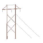 TH-11X
 TH-11XX
TH-13-18.5 TH-13A-21
 TH-14-17.5
 TH-15-17-138
TH-15-18-138 TH-15-19.5-138
 TH-15-21.5-138
 TH-15-23.5-138
TH-15A-17-138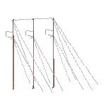 TH-15A-18-138
TH-15A-19.5-138
TH-15A-18-138
TH-15A-19.5-138 TH-15A-21.5-138
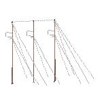
TH-15A-23.5-138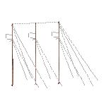 TH-15B-138
 TH-15D-138
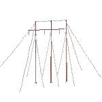 TP-138
TP-138B1 TP-138B2
 TP-138C
 TS-3A-138
TS-3AA-138 TS-4A-138
 TS-5A-138
 TS-5AA-138
TS-138 TS-138A
 TS-138B
 TU-1-138
TH-10 TH-10V4
 TH-10V4X
 TH-10V4XX
TH-10VI TH-10VIX
 TH-10VIXX
 TH-10VO
TH-10VOX TH-10VOXX
 TH-10X
 TH-10XX
TH-11 TH-11V4
 TH-11V4X
 TH-11V4XX
TH-11VI TH-11VIX
 TH-11VIXX
 TH-11VO
TH-11VOX TH-11VOXX
 TH-11X
 TH-11XX
TH-13-20 TH-13A-22.5
 TH-14-20
 TH-15-17-161
TH-15-18-161 TH-15-19.5-161
 TH-15-21.5-161
 TH-15-23.5-161
TH-15A-17-161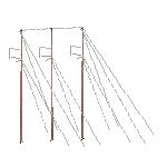 TH-15A-18-161
 TH-15A-19.5-161
 TH-15A-21.5-161
TH-15A-23.5-161 TH-15B-161
 TH-15D-161
 TU-1-161
TH-235-21.5 TH-235-22.5
 TH-235-24.5
 TH-235-27
TH-235-30 TH-235A-21.5
 TH-235A-22.5
 TH-235A-24.5
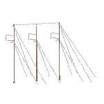
TH-235A-27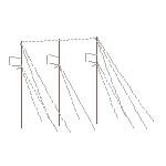 TH-235A-30
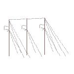 TH-235D
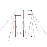 TH-235DX