Madison, WI 53705, U.S.A.
Phone: (608) 238-2171, Fax: (608) 238-9241
Email: info@powline.com
| Home | Search | News | Products |
|
|
610 N. Whitney Way, Suite 160
Madison, WI 53705, U.S.A. Phone: (608) 238-2171, Fax: (608) 238-9241 Email: info@powline.com |
|||
|
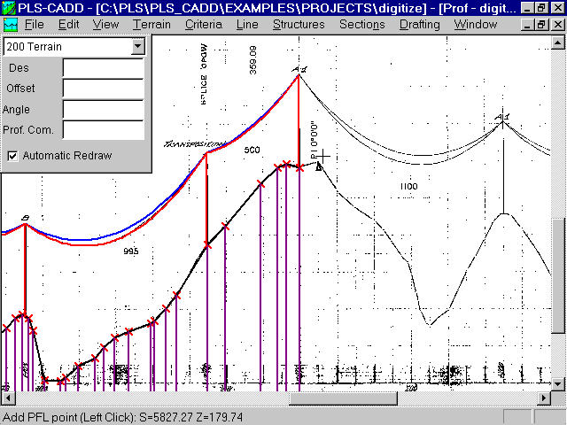
PLS-CADD allows you to superpose DXF drawings and bitmaps in the profile view. The right half of the image above shows a scanned plan & profile sheet bitmap. The left half of the image shows the PLS-CADD profile model in color superposed over the scanned bitmap.
Displaying a drawing or bitmap in the profile view is as simple as specifying the name of the drawing or bitmap and then calibrating it by clicking on a few points and specifying their stations and elevations.
Digitizing points is then done using the Add PFL point command by selecting what kind of point to add (Terrain point in the image above) and clicking where you want to add the point. Any points you add are immediately superposed over the image.
Structures can be automatically added to coincide with digitized attachment points or can be placed using the normal structure editing commands.
Once sections are strung they are sagged to match those of the scanned drawing using the mouse to drag the curve up or down until it coincides with the drawing.