Madison, WI 53705, U.S.A.
Phone: (608) 238-2171, Fax: (608) 238-9241
Email: info@powline.com
| Home | Search | News | Products |

|
610 N. Whitney Way, Suite 160
Madison, WI 53705, U.S.A. Phone: (608) 238-2171, Fax: (608) 238-9241 Email: info@powline.com |
|||
|
The following technical note should be printed out and added to your TOWER manual.
The fourth method consists of replacing some of the truss elements which meet at a planar joint with beam elements. The beam elements will provide some stiffness in all three X, Y and Z directions. It is emphasized here that the main purpose of using beam elements in TOWER is to stabilize planar joints and mechanisms. While shears and moments at the ends of the beam elements are calculated internally and participate in the equilibrium of the tower, they are not used in any design check and they are not included in the TOWER reports. For design purposes, the beam members are still assumed to be loaded axially.
IMPORTANT NOTE:

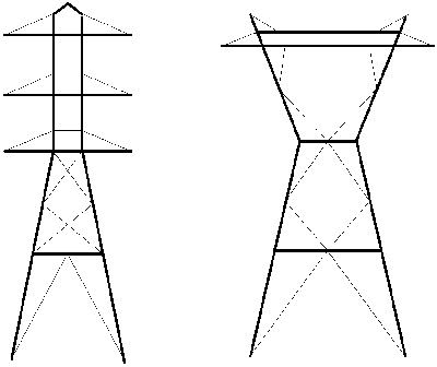
Fig. 2-4-A Beam elements (thick lines)
With the speed and memory of modern computers, we are now recommending that beam elements always be used in certain members of a tower model. While the use of beam elements will slow down your analysis and may limit the size of the tower that you can model, it has the advantage of eliminating the problems of planar joints and mechanisms. This is especially important with towers that contain tension-only members, since unstable mechanisms may develop in these towers at various stages of the analysis. The maximum number of beam elements that can be used (at time of printing of this manual) is given in Section 4.8.
We recommend that all tower members be modeled as beam elements, except diagonals and single horizontal struts. If a diagonal or a strut has an intermediate joint between its ends, then it should also be modeled with beam elements. For example, the thick members in Fig. 2-4-A are modeled as beam elements and the thin members are modeled as truss elements. With such a modeling, all joints, excepts those at the base of the tower, should have no rotational restraint, i.e. the Rotational XYZ restraint code should be 000 in the Geometry/ Primary Joints and Geometry/Secondary Joints menus.
Diagonals and single struts should still be modeled as truss elements. Modeling them as beams would result in an excessively stiff tower since all joints in the model would behave as rigid welded joints instead of more flexible bolted connections.
Example 1.A in Section 7.1.2 shows an alternate way of modeling the tower of Example 1 using beam elements. The analysis results are slightly different for the two models. We would recommend the modeling demonstrated with Example 1.A as the better one.
Using beam elements to stabilize planar joints is also highly recommended if you are running a nonlinear analysis. Fictitious members may not have sufficient stiffness to prevent out-of-plane buckling of planar joints in a nonlinear analysis.
Instabilities can also occur in 3-dimensional trusses which include mechanisms. Mechanisms exist in models which are not fully triangulated (such as diamond-shaped diaphragms) or can develop in towers with tension-only members when two diagonals of the same panel go into compression at the same time.
For example, without the stabilizing member in SECTION C-C of Fig. 2-1 and if modeled as a truss, the entire diaphragm on top of the legs is unstable. A mechanism would develop, with Joints #36 and #36Y moving toward each other and Joints #38 and #38X moving apart.
You can stabilize mechanisms by triangulating them with the addition of fictitious members or by using beam elements. The stabilizing member can be a dummy member with a small cross section area as shown in Fig. 2-1 and as demonstrated in Example 1 of Section 7.1. Or better, you can use beam elements as described in Section 2.1.5.4 and as illustrated in Example 1.A.