2000 Program Improvements
At Power Line Systems we continually improve our software. Below we list some of the more significant enhancements made during the year 2000.
Click here for improvements made in 2001 or here for the most recent enhancements.
- Improved section/modify and section/global display
- Program Limits
- Survey point descriptor increased from 7 to 256 characters
- Terrain comment length increased from 80 to 256 characters
- Maximum number of sets increased from 20 to 60
- Maximum number of feature codes increased from 500 to 1000
- Maximum annotation length increased from 1024 to 4096 characters
- File names can now contain spaces
- Report column widths automatically resized to handle file names in excess of 12 characters
- Attachments
- FLIMAP video integration
- Attachment manager multiple select (Sun Valley 2000 request)
- Bitmap attachments
- Brightness control
- Automatically makes leading white or black edges transparent
- DXF Attachments
- Added support for BLOCK, LWPOLYLINE, BULGE and MTEXT entities
- Can draw using colors from DXF
- Added AutoCAD 2000 export option (prevents AutoCAD crash)
- DXF export of rendered view using solids (allows rendering in CAD system)
- Layer names preserved on export (Atlanta 2000 request)
- Improved Graphics
- Interface Improvements:
- Convenience/Engineering
- Command to shift profile left/right/up/down to fix digitizing calibration problems
- IEEE Std. 738 graph ability to superpose multiple scenarios
- Longitudinal offset on structure attachment coordinates
- Structure loads criteria with different numeric strength factors for different structure components and materials
- Clearance checks between parallel lines (Jackson 2000 request)
- Structure preview window in File Open dialog
- Report width limiter (View/Edit customizations)
- File locking/synchronization for libraries (Sun Valley 2000 request)
- Vang element
- Foundation springs (Sun Valley 2000 request)
- Ability to model wood pole defects and bolt holes (Jackson 1999,2000 request)
- Cross brace optimizer
- Improved features for debugging structures that buckle or otherwise collapse under nonlinear analysis
- Several improvements to graphics
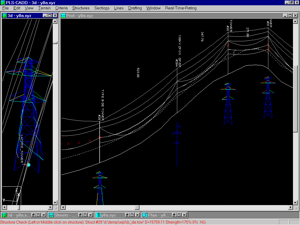
PLS-POLE or TOWER Structures Can be Shown in the Profile View
The following picture shows the new PLS-CADD inset structure feature which lets you see the geometry of structures created with our structure programs in the profile view. These inset structure pictures as well as the structure geometry shown in the 3d view can be color coded to show individual structure member usage.
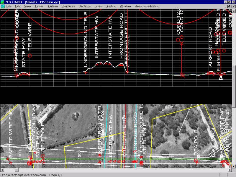
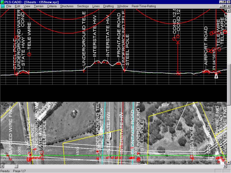
PLS-CADD can now auto-arrange terrain text and labels to prevent collisions between them. The first of the pictures below shows the collisions between terrain comments that you get with the older versions. The next picture shows what you would get with the text auto-arrange enabled.


PLS-CADD has improved section add, modify and edit stringing dialog boxes with graphics showing positions of the various sets.
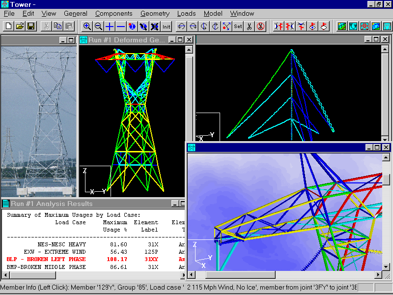
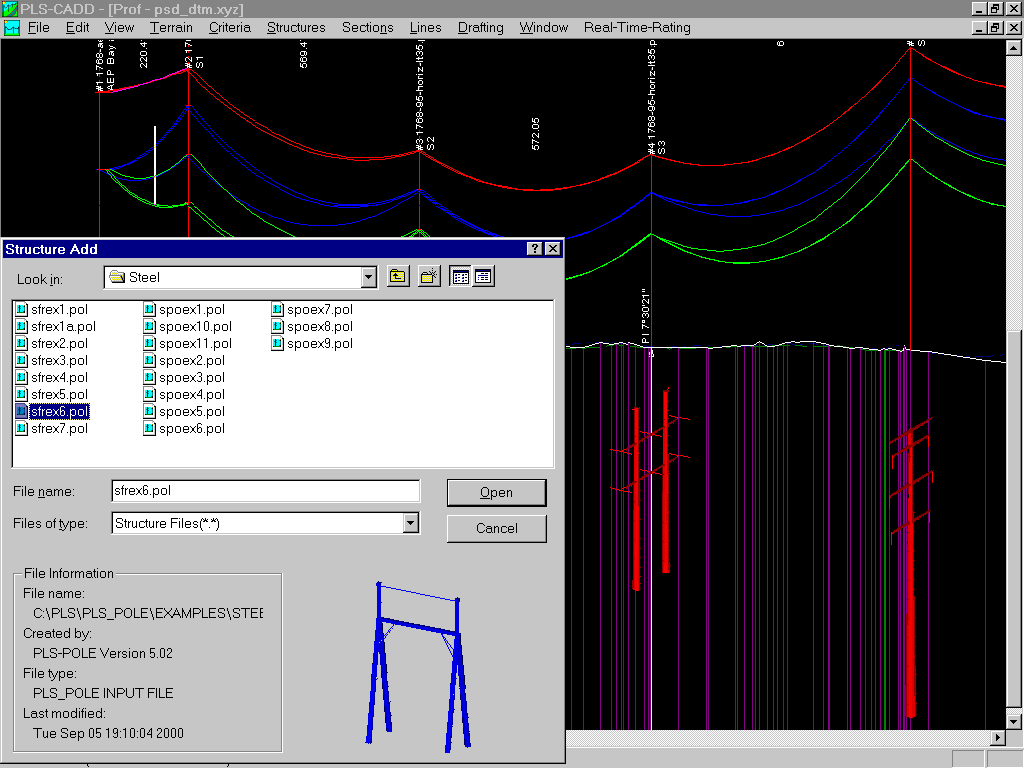
We have revised the File/Open dialog boxes in PLS-POLE and TOWER as well as all of the dialog boxes which let you pick a structure in PLS-CADD to show a picture of the structure. This picture is only available if the structure was created with one of our structure programs.

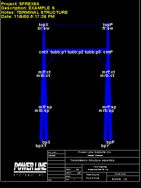
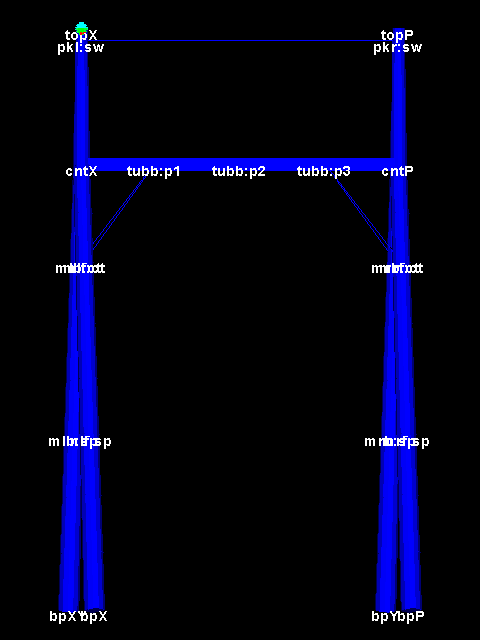
- Automatic text positioning to avoid overlap between text items. Picture on left has joint labels positioned to avoid collisions. Older version on right has text labels on top of each other.
- Addition of text and line annotation (text shown in yellow below)
- Ability to attach bitmap logos and page borders
TOWER 5 now has a plot of leg compression force vs. elevation.

TOWER 5 now has a plot of twist as per EIA/TIA 222

TOWER 5 now has a plot of out-of-plumb as per EIA/TIA 222

© 2018 Power Line Systems All Rights Reserved. Privacy Policy